Bend Relief Size For 16 Gauge Sheet Metal
16 Gauge Stainless Steel Sheet Metal 1 4306 Stainless Plate Buy 16 Gauge Stainless Steel Sheet Metal 16 Gauge Stainless Steel Sheet Metal Sheet Metal 1 4306 Stainless Plate Product On Alibaba Com
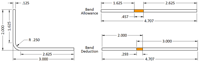
Bend Allowance Sheetmetal Me
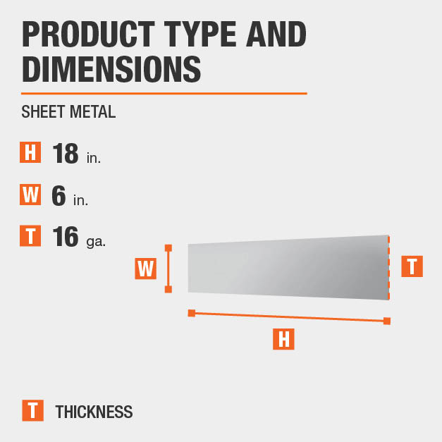
Everbilt 6 In X 18 In 16 Gauge Plain Steel Sheet Metal 801467 The Home Depot

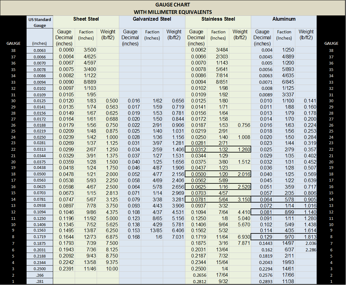
Sheet Metal Gauge To Mm Gauge To Thickness Chart Download Sheet Metal Is Metal Formed By An Industrial Process Into Sheet Metal Gauge Metal Gauge Sheet Metal
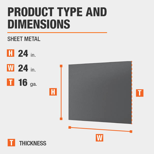
Everbilt 24 In X 24 In 16 Gauge Plain Sheet Metal 800657 The Home Depot

Visual Chart Of Plate Thickness In Guage And Millimeter Cleaning Jewelry Metal Jewelry Jewelry Making

Therefore the bend allowance added to the flange lengths is equal to the total flat.
Bend relief size for 16 gauge sheet metal.

Everbilt 12 In X 24 In 26 Gauge Zinc Plated Sheet Metal 801537 Steel Sheet Metal Steel Sheet Zinc Plating
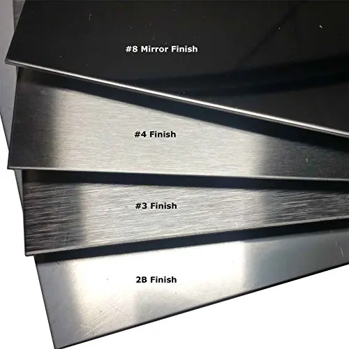
Comparing Stainless Steel Types And Gauges

Wall Section Feature Wall Detail Tectonic Design At Two Union Square Architect Magazine Courtesy N In 2020 Architect Magazine Galvanized Sheet Metal Feature Wall
K Factor Sheetmetal Me

Pin On Process

Pin On Tables Charts For Conversions Et Cetera

Designing For Sheet Metal Fabrication White Paper

How To Control The Warping Of Parts In Thin Sheet Metal Fabricating And Metalworking
What Sheet Metal Shops Wish You Knew Reasonable Tolerances Grain Direction And The Base Flange

Build Your Own Hydraulic Forging Press How To Basic Skills Forging Power Hammer Hydraulic
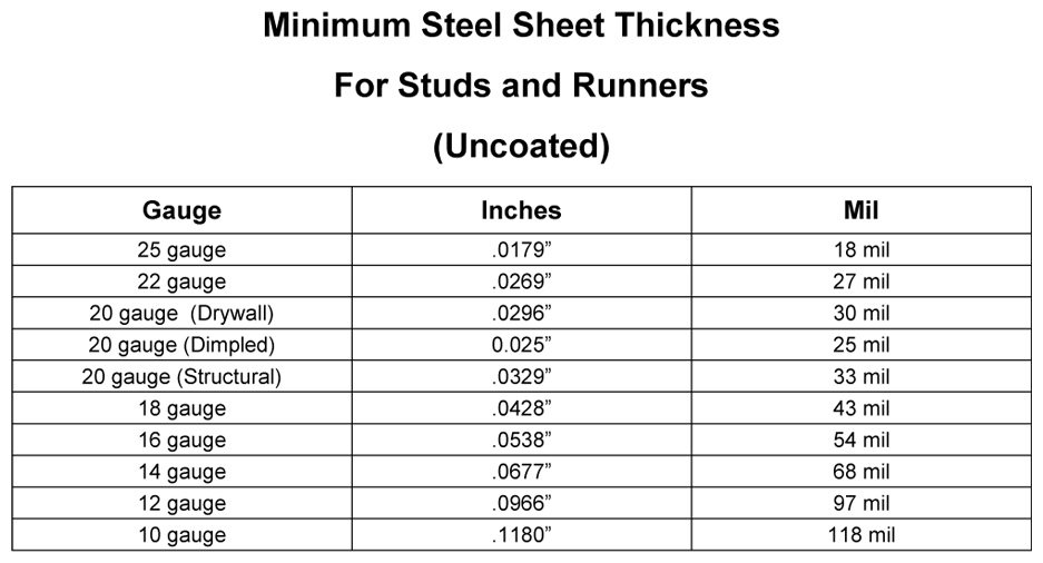
Light Gauge Metal Stud Framing Buildipedia

Mini Bending Brake Metal Working Tools Metal Working Metal Tools

12 X 10 Gauge Sheet Metal Roller Slip Roll Rolling Metalworking Brass Steel Metal Bending Tools Sheet Metal Roller Sheet Metal Fabrication

Slip Roll Stand By Ries Homemade Slip Roll Stand Constructed From Square Steel Tubing Angle Iron And 16 Gau Metal Working Tools Diy Workshop Metal Working
Everbilt 6 In X 24 In 22 Gauge Plain Sheet Metal 800597 The Home Depot

Pin On Furniture Designs

Third Relief Facet Gif 500 724 Trajes De Bricolaje Tecnicas De Dibujo Disenos De Unas
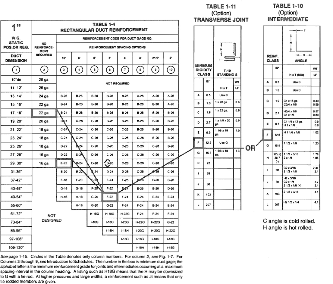
Hvac Duct Construction Standards
Https Encrypted Tbn0 Gstatic Com Images Q Tbn 3aand9gctf5 Nxksu4pilv5ywyfyl1 Wjg1jit Cavw4ekf14vx5cfm6oo Usqp Cau

Whimsie Studio Craft Metal Tools Sheet Wire In Copper Aluminum Brass Nickel Metal Crafts Copper Sheets Copper Art
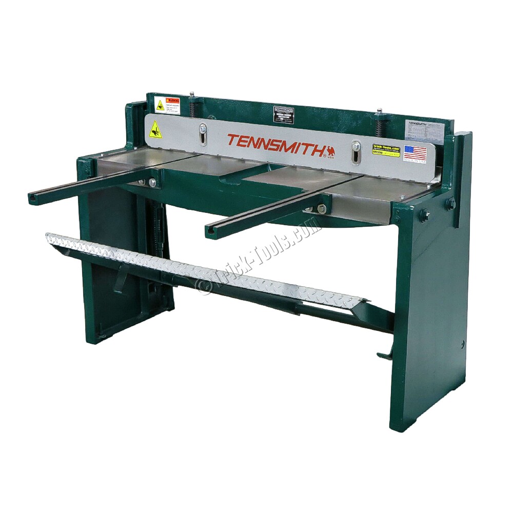
Kick Shear Foot Shear By Tennsmith 52 Inch 16 Gauge Sheet Metal
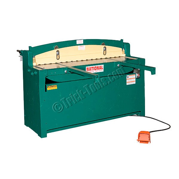
National Sheet Metal Machines Nh5216 52 Inch 16 Gauge Hydraulic Shear
Decorative Metal Trim Molding The Benefits Of Over Wood Metal Decor Metal Trim Moulding Accents
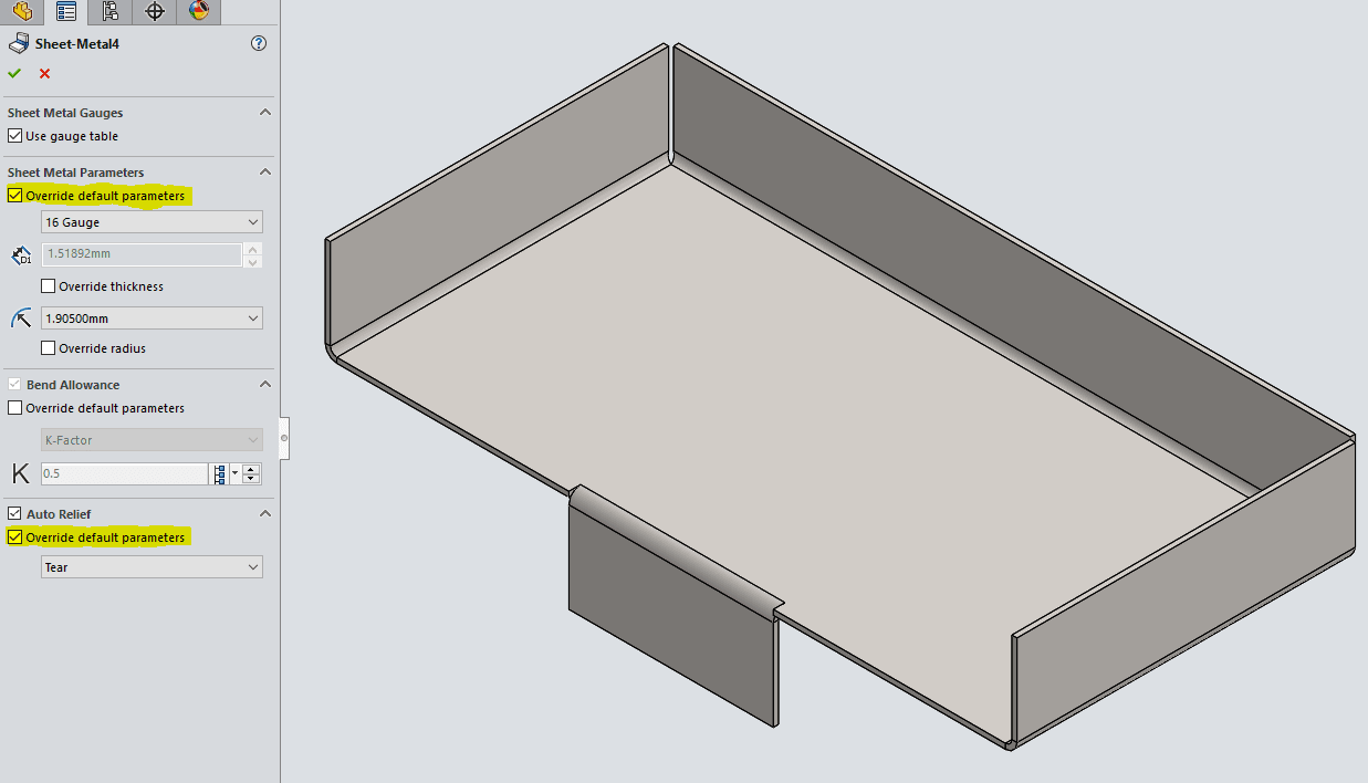
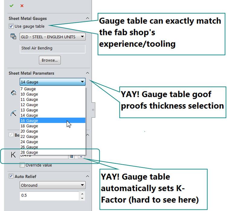
Solidworks 2017 Sheet Metal Options
Source : pinterest.com
